
RTP, the Real-time Transport Protocol, is the protocol that carries the actual audio of a VoIP call. It is defined in RFC 3550, and it provides four things that a raw network connection does not: an identifier for what kind of media the bytes are, a sequence number so the receiver can spot missing or reordered packets, a timestamp so the audio can be played back at the right spacing, and a source identifier so a receiver can tell two senders apart.
RTP is not the protocol that sets up the call. SIP does that. SIP negotiates who is calling whom and agrees where the audio should be sent; RTP then carries the audio between those addresses. The two run independently, over different ports, and often over different network paths. That separation is the single most useful thing to understand about RTP, because it explains most of the faults engineers actually encounter.
RTP at a glance
| Question | Short answer |
|---|---|
| What is it? | A transport protocol for real-time media, defined in RFC 3550 |
| What does it carry? | The encoded audio (or video) of a call, packet by packet |
| What runs underneath it? | Usually UDP over IP, though other transports are possible |
| What negotiates it? | The session description carried inside SIP messages |
| Does it guarantee delivery? | No. RTP has no retransmission, no reservation and no quality of service |
| What is the companion protocol? | RTCP, which reports on delivery quality alongside the media stream |
| Encrypted version? | SRTP, defined in RFC 3711 |
| Typical packet rate | 50 packets per second per direction, one packet per 20 ms of audio |
What RTP does, and what it deliberately does not do
RTP’s own specification is unusually direct about its limits. It states that RTP does not address resource reservation and does not guarantee quality of service for real-time services. There is no acknowledgement, no retransmission, and no flow control in the protocol itself.
That is a design decision, not an omission. In a phone call, a packet that arrives late is worthless. If RTP retransmitted a lost packet, the replacement would arrive after the moment it needed to be played, adding delay to everything behind it. Voice tolerates a small amount of loss far better than it tolerates variable delay, so RTP simply keeps sending and lets the receiver cope with gaps.
What RTP provides instead is the metadata a receiver needs to cope intelligently:
- Payload type identification, so the receiver knows how to decode the bytes.
- Sequence numbering, so it can detect loss and reordering.
- Timestamping, so it can reconstruct the original spacing between samples.
- Delivery monitoring, through the companion RTCP protocol.
Everything else, including recovering from loss and smoothing out jitter, happens above RTP in the receiving application.
How a voice stream becomes RTP packets
A continuous audio signal has to be cut into pieces before it can be sent over a packet network. The process is the same on every VoIP endpoint.
- The microphone or gateway produces a stream of audio samples at a fixed rate, commonly 8,000 samples per second for narrowband telephony.
- A codec encodes those samples. G.711 encodes each sample independently as one byte. Frame-based codecs such as G.729 encode fixed blocks, typically 10 ms at a time.
- A fixed amount of encoded audio is gathered into one packet. The amount is called the packetisation interval, or
ptime, and 20 ms is the default for almost every audio encoding in RFC 3551. - An RTP header is prepended, then UDP and IP headers, and the packet is sent.
- This repeats 50 times per second, in each direction, for the duration of the call.
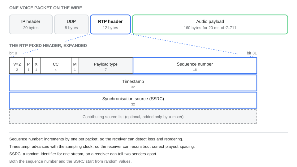
For G.711 at 20 ms, the payload is 160 bytes. That number is worth remembering, because it appears in packet captures constantly and makes the rest of the arithmetic easy to check.
What is inside an RTP packet
The RTP fixed header is twelve bytes and is present in every packet. The fields in order are:
- Version (2 bits), always 2 in current use.
- Padding (1 bit), indicating the payload has been padded, which matters for some encryption schemes.
- Extension (1 bit), indicating a header extension follows.
- CSRC count (4 bits), the number of contributing source identifiers appended after the fixed header.
- Marker (1 bit), whose meaning is defined by the profile. In audio it commonly marks the first packet of a talkspurt after silence.
- Payload type (7 bits), identifying the encoding.
- Sequence number (16 bits), incrementing by one for each packet sent.
- Timestamp (32 bits), reflecting the sampling instant of the first byte in the payload.
- SSRC (32 bits), the synchronisation source identifier for this stream.
Two details in the specification are easy to miss and useful to know. First, both the initial sequence number and the SSRC are chosen randomly rather than starting at zero. The random sequence number makes known-plaintext attacks harder if the stream passes through something that encrypts it, and the random SSRC minimises the chance that two sources in the same session collide. Second, the contributing source list is not part of the twelve byte fixed header. It appears only when a mixer combines several sources into one stream.
How the payload type tells the receiver what the bytes mean
The seven bit payload type field is a number, not a name. RFC 3551 assigns static numbers to a set of long-standing audio encodings, and reserves a range for encodings negotiated dynamically during call setup.
| Payload type | Encoding | RTP clock rate | Note |
|---|---|---|---|
| 0 | PCMU (G.711 mu-law) | 8,000 Hz | The most widely interoperable audio format |
| 8 | PCMA (G.711 A-law) | 8,000 Hz | The G.711 variant used across most of the world outside North America and Japan |
| 9 | G722 | 8,000 Hz | Wideband audio, but see the note below |
| 13 | CN | 8,000 Hz | Comfort noise, defined in RFC 3389 |
| 18 | G729 | 8,000 Hz | Low bitrate, frame based |
| 96 to 127 | Dynamic | Negotiated | Used for Opus, telephone-event and anything else agreed at setup |
The G.722 entry contains one of the best known oddities in real-time media. G.722 samples audio at 16,000 Hz, but its RTP clock rate is listed as 8,000 Hz. RFC 3551 explains this directly: the value was assigned erroneously in the earlier RFC 1890 and has been retained unchanged for backward compatibility. Implementations therefore have to know that for this one payload type the clock rate in the table does not match the sampling rate. It is a good example of why RTP behaviour is worth reading from the specification rather than inferred from first principles.
Note also that the payload type is a per-packet field. A sender may change it mid-stream within the same media type, which is exactly how comfort noise and DTMF events are interleaved into an ongoing audio stream.
How the two sides agree where to send audio
RTP itself contains no addressing beyond what IP and UDP provide. The addresses come from the session description exchanged during call setup, using the offer and answer model defined in RFC 3264 and the format defined in RFC 4566.
The offering side includes a media line stating the media type, the port it will listen on, the transport profile, and the payload types it supports, along with attribute lines mapping dynamic payload types to codec names and stating the packetisation interval. The answering side responds with its own port and the subset it accepts. From that point each side knows an address and port to send to.
By convention from RFC 3550, RTP uses an even UDP port number and RTCP the next odd one. That convention is increasingly superseded. RFC 5761 describes how RTP and RTCP can be multiplexed onto a single port, signalled in the session description, which halves the number of ports a NAT device has to keep open. Modern WebRTC-derived stacks multiplex by default; traditional SIP endpoints often do not.
Two practical consequences follow. Media ports are allocated dynamically from a range rather than fixed, so firewall rules for media cannot be as narrow as those for signalling. And the ports advertised in the session description are the ports that must actually be reachable, which is where address translation causes trouble.
Signalling and media take different paths
SIP messages are routed hop by hop through proxies. Each proxy can inspect and forward the request, and the signalling path may pass through several intermediaries between the caller and the called party.
The media does not have to follow that path at all. Unless something in the middle deliberately intervenes, the session description tells each endpoint the other’s media address directly, and the RTP flows between them over whatever route the network chooses. A call can therefore traverse three proxies on the signalling side while the audio takes a single direct hop. The signalling path establishes the call, but the audio never has to follow it.
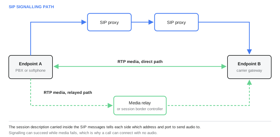
In practice, something in the middle usually does intervene. Session border controllers and media relays rewrite the session description so that both endpoints send their audio to the intermediary, which then forwards it. Providers do this for several legitimate reasons: to work around address translation, to enforce topology hiding, to transcode between codecs the two sides do not share, to apply lawful intercept, and to keep media inside a controlled network. The cost is an extra hop of delay and a device that has to handle every packet of every call.
This separation is the root cause of the most common VoIP fault report. When a call rings, answers, and has silence in one or both directions, the signalling worked and the media did not. The diagnosis is almost always about addresses and firewall rules on the media path rather than anything in the SIP exchange. Router features that rewrite SIP packets in transit are a frequent culprit, covered in our guide to SIP ALG.
What RTCP adds
RTCP, the RTP Control Protocol, is defined in the same RFC and runs alongside every RTP session. It carries no media. Its job is to report on the delivery of the media, periodically and in both directions.
Sender reports carry the sender’s packet and byte counts along with a mapping between the RTP timestamp and a wallclock reference, which is what makes it possible to synchronise separate audio and video streams. Receiver reports carry the numbers that matter for diagnosing quality: the fraction of packets lost since the previous report, the cumulative number lost, the highest sequence number received, an estimate of interarrival jitter, and timing information used to derive round-trip time.
Two points about RTCP are worth holding on to.
It is a measurement channel, not a control channel. RTCP reports that quality is poor. It does not fix it, and in the base specification it does not instruct the sender to do anything about it.
Its bandwidth is deliberately tiny. The specification recommends that RTCP traffic be limited to a small fraction of the session bandwidth, so reports are infrequent. RTCP is excellent for post-call quality analysis and mediocre as a real-time alarm.
Because RTCP reports come from the far end, they are also the only view you get of what the other side actually received. Local statistics tell you what you sent and what arrived at you. RTCP tells you what arrived at them.
How the receiver turns packets back into sound
Packets leave the sender evenly spaced and arrive unevenly. The receiver’s job is to undo that.
The jitter buffer holds arriving packets briefly, reorders them by sequence number, and releases them to the decoder at the correct spacing derived from the timestamps. A larger buffer absorbs more variation in arrival time and adds more delay. A smaller buffer adds less delay and discards more late packets. Most implementations adapt the buffer size continuously to observed conditions.
Packet loss concealment fills the gaps. When a packet does not arrive in time, the decoder generates a substitute, typically by extrapolating from the previous frame. Concealment works well for isolated losses and poorly for consecutive ones, which is why the distribution of loss matters more than the total percentage. Two per cent loss spread evenly is usually acceptable. Two per cent arriving as occasional bursts of ten consecutive packets is audible as dropouts.
Late packets are the same as lost packets. A packet that arrives after its playout moment has passed is discarded. This is why network jitter and packet loss produce similar symptoms, and why measuring them separately matters. Our guide to latency, jitter and packet loss covers the network side of this in detail.
Silence, comfort noise, and the packets that are not sent
Not every 20 ms of a call produces a packet. Many endpoints implement voice activity detection and stop transmitting during silence, which is called discontinuous transmission or silence suppression.
If the sender simply stopped, the receiver would play digital silence, and the person listening would assume the call had dropped. RFC 3389 solves this with a comfort noise payload: the sender transmits an occasional small packet describing the noise characteristics of the background, and the receiver synthesises a matching low-level hiss locally. Some codecs implement their own equivalent internally rather than using the separate CN payload type.
Silence suppression saves bandwidth, and it interacts badly with several things worth knowing about. Automated systems that measure audio energy can misread synthesised comfort noise. Speech recognition endpointing behaves differently when the far end stops sending during pauses. And some legacy equipment handles the payload type switch poorly, producing clipped first syllables after a pause. On outbound campaigns and machine-driven calls it is often better to disable it.
Why DTMF is carried outside the audio
Keypad tones present a problem. Low bitrate codecs are optimised for speech, and passing a pure dual tone through them can distort it enough that the receiving system fails to recognise the digit. Sending the tones as audio also makes them impossible to detect reliably after transcoding.
RFC 4733 defines a named event payload that carries the digit itself as structured data rather than as sound: the event code, a volume, a duration and an end marker, sent in RTP packets using a dynamically assigned payload type. The receiving side regenerates the tone locally if it needs one. This is the method most commonly labelled RFC 2833 in equipment menus, after the earlier RFC it replaced.
The alternative is to send digits in SIP INFO messages, which moves them onto the signalling path entirely. This works but is less widely supported and decouples the digit from the audio timeline. Mismatched DTMF methods between two ends produce a characteristic fault: audio is perfect, and menu navigation silently fails.
What SRTP changes
Plain RTP is unencrypted. Anyone positioned on the network path can capture the packets and reassemble the audio with standard tools, and can read the payload type, sequence numbers and SSRC in the clear.
SRTP, defined in RFC 3711, adds confidentiality for the payload, integrity protection and replay protection, while leaving the RTP header readable so that intermediaries can still route and monitor the stream. It is designed to add very little overhead, which matters when you are sending 50 packets per second per call.
The critical operational point is that SRTP needs its keys from somewhere. Where they are carried inline in the session description, they travel inside the SIP messages, so running SRTP over unencrypted SIP publishes the key alongside the encrypted media. SRTP and TLS on the signalling are complementary, and enabling one without the other leaves an obvious gap.
RTP and network address translation
RTP over UDP has no handshake, which makes address translation harder than it is for TCP. An endpoint behind NAT advertises its private address in the session description, and the far end dutifully sends audio to an address that is unreachable.
The convention that solves most of this is symmetric RTP, described in RFC 4961: an endpoint sends RTP from the same port on which it expects to receive it. This lets the far side, or an intermediary, learn the real public address and port from the packets actually arriving and send audio back to that, rather than trusting what was advertised. The technique is often called latching.
Symmetric RTP explains a familiar asymmetry in fault reports. If only one side is behind NAT, audio usually flows once that side sends its first packet, so the person behind NAT hears the far end and the far end hears nothing until the first outbound packet arrives. If both sides are behind NAT with nothing in the middle, direct media often fails entirely, which is why providers relay media rather than leaving endpoints to find each other.
How much bandwidth an RTP stream actually uses
Codec bitrate is not stream bitrate, and the difference is larger than most people expect.
A G.711 call at 20 ms packetisation carries 160 bytes of payload per packet. Add 12 bytes of RTP header, 8 of UDP and 20 of IPv4, and each packet is 200 bytes at the IP layer. At 50 packets per second that is 80 kbit/s per direction, against a nominal codec rate of 64 kbit/s. Counting Ethernet framing, preamble and interframe gap pushes the figure to roughly 95 kbit/s per direction.
The overhead is proportionally worse for low bitrate codecs. G.729 at 20 ms carries 20 bytes of payload against 40 bytes of headers, so two thirds of every packet is addressing rather than audio. A nominal 8 kbit/s codec consumes about 24 kbit/s at the IP layer.
Raising the packetisation interval to 40 ms halves the packet rate and therefore halves the header overhead. It also adds delay in both directions and doubles the amount of audio lost when a single packet goes missing, which makes concealment harder. Most deployments keep 20 ms for that reason. Codec choice is covered further in our guide to voice codecs.
Common misconceptions
“SIP carries the audio.” SIP carries the negotiation. RTP carries the audio, on different ports and often over a different path.
“RTP is a transport protocol like TCP.” RTP runs on top of a transport, almost always UDP. It adds media semantics; it does not replace the transport layer.
“Opening the SIP port is enough.” Signalling and media use different ports. A firewall that permits 5060 and nothing else produces calls that connect with no audio.
“Packet loss percentage tells you how bad it will sound.” Distribution matters more than total. Bursts are far more damaging than the same number of isolated losses.
“Wideband audio negotiated end to end means the call is wideband.” Only if every hop preserves it. Any transcoding step in the middle collapses the stream to the lowest common denominator.
“RTCP will tell me about problems as they happen.” RTCP is deliberately low bandwidth and reports periodically. It is a quality measurement tool, not a real-time alarm.
“SRTP secures the call.” SRTP secures the media. Without TLS on the signalling, the negotiation, including inline keys, is still readable.
Where didlogic fits
didlogic operates the voice infrastructure layer, which means it terminates the RTP media path from customer endpoints and carries it onward toward the destination network. Several details of how that works are documented publicly and are directly relevant to the topics above.
Media addressing. didlogic publishes fixed signalling addresses for its regional SIP gateways, but notes in its FAQ that media addresses are numerous and change frequently, so firewall policy should permit RTP audio on the published port range rather than from a narrow source list. Customers whose security policy cannot accommodate that can request a media address list from support. This is the practical form of the general point that media and signalling need different firewall treatment.
Codec handling. The supported codec set for SIP trunk connections is documented as G.711 mu-law, G.711 A-law, GSM and G.729, with G.722 supported but of limited availability. The documentation is explicit about why: many carriers do not preserve wideband audio end to end, so G.722 may not survive all the way to the subscriber’s handset. An endpoint can force a specific codec and the session border controller will comply where possible, which is the mechanism that avoids an unnecessary transcoding hop.
DTMF. Both in-band tones and RTP named events under RFC 2833 and RFC 4733 are supported, which matters when an outbound call has to navigate an automated attendant.
Media encryption. SRTP is available to encrypt the RTP stream, including on inbound DID products rather than only on the outbound leg, alongside TLS on the signalling. The encrypted calls documentation sets out the combinations and what each protects.
What remains on your side is the endpoint behaviour: the codec list you offer, the packetisation interval you set, whether you enable silence suppression, how your jitter buffer is tuned, and whether your firewall and any address translation between your endpoints and the network allow the media to flow in both directions.
Frequently asked questions
What is the difference between RTP and SIP?
SIP is a signalling protocol. It sets up, modifies and ends sessions, and carries the session description that says where media should go. RTP is a media transport protocol. It carries the encoded audio itself. They use different ports, and the media often takes a different network path from the signalling.
Does RTP use TCP or UDP?
Almost always UDP. RTP is defined independently of the underlying transport, and framing for connection-oriented transports exists, but UDP is the normal choice because retransmission is useless for real-time audio and the delay it introduces is harmful.
What port does RTP use?
There is no single port. Ports are allocated dynamically from a range and advertised in the session description for each call. The traditional convention uses an even port for RTP and the next odd port for RTCP, though RFC 5761 allows both on one port.
Why can a call connect but have no audio?
Because signalling succeeded and media did not. The usual causes are firewall rules that permit the SIP port but not the media range, address translation that advertises an unreachable private address, or a device in the path that rewrites the session description incorrectly.
Does RTP retransmit lost packets?
No. The base protocol has no retransmission. The receiver conceals gaps by extrapolating from previous audio, which is effective for isolated losses and much less so for bursts.
What is the SSRC used for?
It identifies one stream from one synchronisation source, so that a receiver handling several streams can keep them apart. It is chosen randomly, and implementations are required to detect and resolve the rare case where two sources pick the same value.
Is RTP encrypted?
Not by default. SRTP provides encryption, integrity and replay protection for the media while leaving the RTP header readable. It needs a key exchange, and where the keys are carried in the session description, the signalling must also be encrypted for the arrangement to be meaningful.
What packetisation interval should I use?
20 ms is the default for nearly every audio encoding in RFC 3551 and is the safe interoperable choice. Larger intervals reduce header overhead but add delay and make each lost packet more damaging.
Continue learning
